Solar Cells

CRACK DETECTION in Si WAFERS & SOLAR CELLS
Resonance Ultrasonic Vibrations (RUV) Technology
- High reliability: 91 – 95 percent
- High throughput: < 2 seconds/wafer
- Non destructive
- In-line & Off-line configurations
- UL certified
RUV TECHNOLOGY
The Resonance Ultrasonic Vibrations (RUV) technique was developed for off-line and in-line non-destructive crack and stress detection in full-size silicon solar cells. The RUV methodology relies on a deviation of the resonance frequency response curve measured on a wafer with peripheral or bulk millimeter-length crack and identical non-cracked wafers.
The crystalline silicon (cSi) wafer is a large contributor to the overall cost of the solar cell. To reduce production cost, solar cSi wafers are sliced thinner with thicknesses down to 150 microns with a target of 100 microns. In parallel, wafer areas have also been increased with the typical size of 156 mm x 156 mm. These technological trends make cSi wafer handling in production more challenging and reduce the yield of solar cell lines due to increased wafer and cell breakage. In-line wafer breakage also reduces equipment throughput as a result of down time.
The RUV technology allows to (1) reject mechanically unstable Si wafers after ingot cutting before they are introduced into further cell processing, (2) identify the wafers with cracks and high stress in real-time to avoid in-line breakage, (3) detect cracked cells before they will be laminated into modules to avoid panel efficiency reduction and product return from the field, and (4) identify cells with sub-millimeter size seed cracks using RUV integrated with Activation Station. RUV system also serves as a process control tool to increase yield by eliminating production flaws caused by mechanical defects.
FREQUENCY CURVE
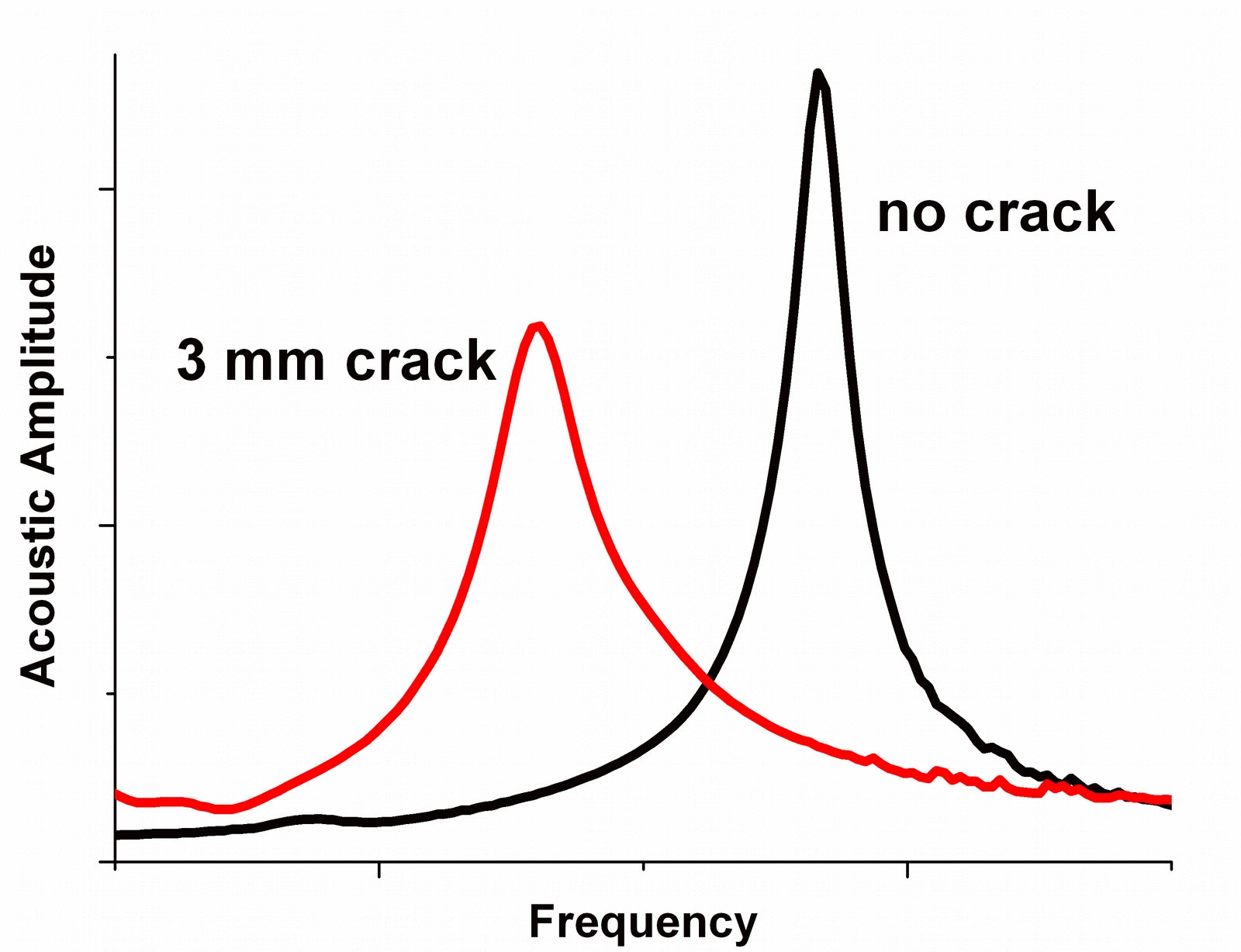
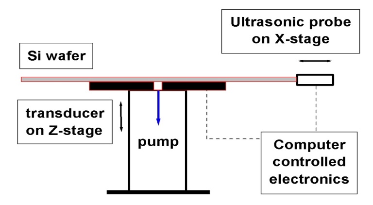
Through a resonance frequency curve selected from a broad range (20 - 250 kHz), the RUV method enables crack detection with simple criteria for wafer or cell rejection. A crack introduced into Si wafer alters the RUV peak parameters: amplitude, bandwidth and peak position. This is illustrated in Figure 1 for two identical Si wafers. Specifically, the crack in the wafer shows the following features: (1) a frequency shift of the peak position; (2) an increase of the bandwidth, and (3) a reduction of the amplitude. Therefore, the RUV approach is based on a fast measurement and analysis of a specific resonance peak and rejection of the wafer if peak characteristics deviate from the normal non-cracked wafers. In Figure 2 a schematic of the RUV system layout is shown.
The sensitivity of the system, which refers to the length of the cracks, is adjustable to the needs of the user. The rejecting method is based on a statistical approach. In case studies, the accuracy of this method was between 91 - 95%. That means that after RUV inspection the breakage caused by cracked wafers or cells is reduced by a factor of 10. ROI of the RUV system is 6 to 12 months. RUV system qualification in PV production: tact time 1.75sec/cell (peak), 24/7 operation, 97% up-time, 12M cells.
IN LINE & OFFLINE CONFIGURATIONS
Fully automatic In-line, Off-line and Quality Control RUV Tools are currently available for wafers, cells, and module production. RUV can be optionally integrated with imaging equipment. For more technical information, please visit Ultrasonic Technologies web-site www.ultrasonictech.com